Structural design codes: from manual checks to automated verification
The path from an FEM model mesh to a signed code-compliance report often takes more effort than the analysis itself. A von Mises stress field does not answer what the reviewer is actually checking: whether the structure passes Eurocode 3, AISC 360, DNV, or ISO 19902. This article walks through what design codes actually require, where manual verification consumes the most time, what shifts under automated checking, and which tasks stay on the engineer.
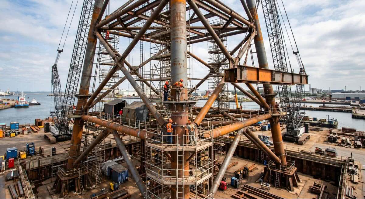
What design codes actually regulate
Design codes carry the structure of the entire verification process. They define material design resistances, partial safety factors, stability-checking methodology, fatigue assessment rules, and connection design formulas. Without these formulas, an FEM simulation remains a set of stress plots with no legal standing.
Eurocode 3 (EN 1993) covers steel structure design for buildings and civil engineering works: 20 parts span general rules, joints, fatigue, bridges, towers, and silos. In October 2025, updated versions of EN 1993-1-4 (stainless steels), EN 1993-1-6 (shell stability), and EN 1993-1-9 (fatigue) were released. AISC 360-22 governs steel building design in the US, allowing both ASD and LRFD approaches. DNV-RP-C203 (2024) defines fatigue assessment of offshore structures through S-N curves and stress concentration factors. API RP 2A-WSD remains the base document for fixed offshore platforms, and ISO 19902 regulates fixed steel offshore structures in the oil and gas industry.
Each document defines specific checks, not general principles. EN 1993-1-1 formalizes section checks for bending, axial force, shear, and their combinations, plus member stability through the reduction factors χ. AISC 360 prescribes interaction equations such as H1-1 for combined loading and stability formulas based on effective length. EN 1993-1-9 and DNV-RP-C203 work with S-N curves and fatigue damage accumulation under the Palmgren-Miner rule, while EN 1993-1-8 covers the design of bolted and welded connections by specific detail categories.
The shift in mindset is clear. The engineer’s task is not to report a peak stress but to prove that the utilization ratio for each criterion (bending, shear, stability, fatigue, connections) stays below unity under every code-mandated load combination.
What manual verification actually involves
Between the solver run and a report the reviewer will accept, several mandatory tasks remain that the solver itself does not handle.
Stress linearization along the Stress Classification Line (SCL) is mandatory under several codes. Under ASME Section VIII Division 2 Part 5, von Mises stress cannot be compared with the allowable S directly. The tensor decomposes into primary membrane Pm, bending Pb, secondary Q and peak F components, each with its own limit: Pm ≤ S, Pm + Pb ≤ 1.5S, and Pm + Pb + Q ≤ 3S. Comparing von Mises directly to the allowable without decomposition remains the single most common reason FEA reports get rejected at review.
Mesh convergence documentation runs on the same principle. The standard criterion is a peak-stress change below 5% between two refinement levels. A report without demonstrated convergence at critical points is not accepted.
Then come the load combinations. The modern Eurocode approach generates hundreds of sums, and six hundred cases are easy to reach on a typical steel structure. The engineer extracts governing loads from this set, runs section checks against them, and consolidates the results into one document.
On top of that comes the report itself. A typical ASME report structure carries thirteen mandatory sections, from design conditions and materials through buckling proofs to final certification.
Where the manual cycle slows down
Code updates regularly trigger rework. DNV-RP-C203 (2024) revised the B1 to C2 S-N curves and removed the grit-blasting factor for ground welds, which changes the calculated fatigue endurance for typical monopile details. Any project where fatigue was assessed under the previous edition needs a full recalculation of affected details and a rewrite of the corresponding report sections.
A similar effect appears without any code change. Reports with missing sections, errors in stress categorization, or no convergence documentation go through two or three rounds of reviewer revisions and add weeks to the project schedule. When the calculations live in Excel and a word processor, every model change pushes the work back to data export and table rewriting.
A separate quality issue runs in parallel: visibility of individual load combinations. On an envelope view of six hundred cases, the engineer does not see the specific combination behind the worst result, and the averaged data does not show which loading scenario actually drives the critical value.
What automated verification covers
The category of software that closes the gap between FEM output and a signed code-compliance report runs on a single chain: automatic recognition of structural elements, application of the chosen standard’s formulas to each one, and report assembly without manual stitching. Implementations exist both as extensions to FEA environments (Ansys, Femap, Simcenter 3D) and as standalone tools with a built-in Nastran solver.
Element recognition removes a significant part of the manual model tagging. Collinear beam elements get merged into a single member for stability checks. Shell fields between stiffeners are identified as panels, while weld nodes and bolted joint points are tagged automatically. From there, the chosen standard’s checks apply to each element: bending, shear, lateral-torsional buckling, plate buckling, fatigue against the appropriate S-N curves, and bolted and welded connection design. The utilization ratio for each criterion comes out directly and is tied to a specific load combination.
Governing loads get extracted from the full set of combinations without manual sorting, and with software like https://sdcverifier.com/, the engineer receives a list of combinations that produce the maximum for each criterion, with their percentage contribution, instead of an envelope picture. This restores the link between numerical output and physical behaviour that gets lost when six hundred cases are processed by hand.
The report comes together in a single pass: geometry, materials, boundary conditions, load matrix, mesh convergence, check results, and conclusions against each standard. After a model change or a standard update, the report regenerates without manual rewriting, with export to Word, PowerPoint, and PDF.
What automation does not replace
A compressed verification cycle does not transfer engineering responsibility for the result. The NAFEMS Simulation Governance Working Group puts it directly: verification and validation stay with the engineer, not the software vendor. A code-check algorithm is only as reliable as the boundary conditions, problem setup and assumptions feeding it.
This shows up most clearly when the analysis model changes. Switching from a linear-elastic to an elastic-plastic run at the click of a button changes the mathematical model and the assumption set behind it. The code-check algorithm will execute on any input, but the legally binding conclusion comes from the engineer who signs the report.
Effect on schedule and project quality
The effect of moving to automated verification shows up first in responsiveness to change, not in percentage savings on a single project. When DNV-RP-C203 updates, recalculation runs on the same model without manual re-export to Excel. When the geometry shifts after a CAD iteration, the report rebuilds in one pass instead of a week of reformatting. When the reviewer sends comments, the affected sections are updated in place without revisiting the whole document.
In a real engineering office workload, this cuts not only the time spent on the code check itself but also the number of revision cycles on the approval side. Structural verification stops being the main constraint on the project schedule.
Comments
Comments are loaded when you choose to open them, which keeps the page faster and lighter.